Test Sheet: X.Touch 2.0
Yocto Version
This test sheet targets the walnascar release of the NXP BSP. If you are working on a different Yocto version, refer to the corresponding test sheet on the meta-engicam-nxp branch for your release.
Test sheet SmarCore MX8M Plus XTOUCH 2.0
Test sheet
Version: 1.0
Preliminary
Creation of engicam-evaluation-image-mx8 image for sdcard booting and same image for eMMC programming.
Board Type: XTOUCH 2.0
SOM Type: SmarCore MX8M Plus
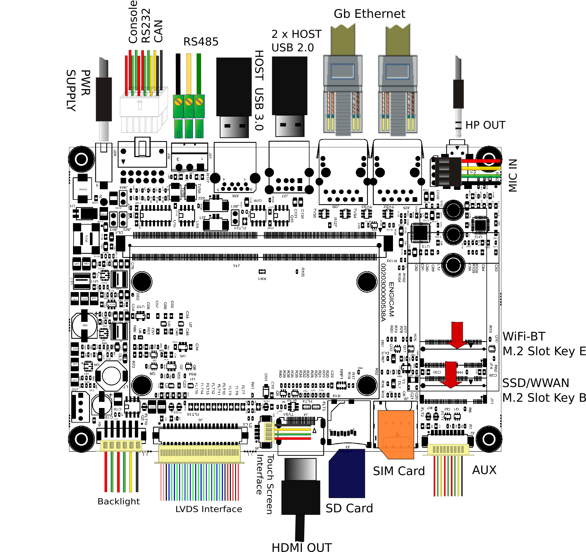
U-boot tests
| Test | Status |
|---|---|
| eMMC Enviroment saving | OK |
| Sdcard Enviroment saving | OK |
| Ethernet | OK |
| Boot from eMMC | OK |
| Boot from sdcard | OK |
| USB | OK |
| Serial Download | N/A |
Test Notes:
eMMC Environment saving
Sdcard environment saving
Close the connector JM1:
Ethernet
Once the serverip has been saved connect the board at J25:
The output should be:
Do the same test on port J26. The output should be:
Boot from eMMC
Open the connector JM1:
The output should be:
Boot from sdcard
Close the connector JM1:
The output should be:
USB
Plug USB storage devices in J27/J28 connectors (both USB buses are in host mode for OTG serial download is not available on XTOUCH 2.0):
The output should be:
starting USB...
Bus usb@38100000: Register 2000140 NbrPorts 2
Starting the controller
USB XHCI 1.10
Bus usb@38200000: Register 2000140 NbrPorts 2
Starting the controller
USB XHCI 1.10
scanning bus usb@38100000 for devices... 2 USB Device(s) found
scanning bus usb@38200000 for devices... cannot reset port 3!?
4 USB Device(s) found
       scanning usb for storage devices... 3 Storage Device(s) found
The output should be (for example):
USB device tree:
  1  Hub (5 Gb/s, 0mA)
  |  U-Boot XHCI Host Controller
  |
  +-2  Mass Storage (480 Mb/s, 100mA)
       Lexar USB Flash Drive AAGQFTGHNCK9GDXE

  1  Hub (5 Gb/s, 0mA)
  |  U-Boot XHCI Host Controller
  |
  +-2  Hub (480 Mb/s, 2mA)
  | |
  | +-3  Mass Storage (480 Mb/s, 200mA)
  |      Verbatim STORE N GO 072125AD020B8F58
  |
  +-4  Mass Storage (5 Gb/s, 224mA)
        USB  SanDisk 3.2Gen1 04010b53be303fea317bff34a9d8b86
Once done do:
to safely remove storage devices.
Serial Download
Open JM1 and close JM3 jumper to enable serial download. Connect the board with the source machine (i.e. the machine you are downloading the images from) by using the board's OTG header (N/A).
Power on the board.
From source machine check if an USB device for serial download is detected:
Output:
uuu (Universal Update Utility) for nxp imx chips -- lib1.5.141

Connected Known USB Devices
    Path     Chip    Pro     Vid     Pid     BcdVersion
    ==================================================
    1:1  MX865   SDPS:   0x1FC9 0x0146   0x0002
Here we see a device is detected. Then type:
And wait for the download and flash of eMMC to finish.
Kernel Linux tests
| Status | Test | Note |
|---|---|---|
| OK | Ethernet 0 (J25) | see note1 |
| OK | Ethernet 1 (J26) | see note1 |
| OK | USB 2.0 (J27) | tested with USB stick |
| OK | USB 3.0 (J28) | tested with USB stick |
| OK | SD card (JM1 closed) | boot system from SD card |
| OK | eMMC card (JM1 open) | boot system from eMMC |
| TBT | UART 232 ttymxc0 (J32) | see note2 |
| OK | UART 485 ttymxc2 (J31) | see note3 |
| OK | Linux Console (J32) | |
| N/A | WIFI | |
| N/A | BLUETOOTH | |
| OK | RTC | see note4 |
| OK | Reboot | |
| TBT | LVDS | see note5 |
| TBT | Backlight | see note6 |
| TBT | Touchscreen | see note7 |
| OK | HDMI | |
| N/A | Audio | see note8 |
| TBT | CAN 0/CAN 1 (J32) | see note9 |
| TBT | M.2 Key E PCIe (Wifi/BT) | see note10 |
| N/A | M.2 Key B PCIe (Sata) | |
| OK | GPU | see note11 |
| OK | VPU | see note12 |
Note
Note 1
Connect board's ethernet with your machine's one.
On your machine launch iperf3 server by typing:
On board launch iperf3 in client mode:
Using the IP address of your server machine.
Output:
Connecting to host 192.168.10.1, port 5201
[  5] local 192.168.10.85 port 47390 connected to 192.168.10.1 port 5201
[ ID] Interval           Transfer     Bitrate         Retr  Cwnd
[  5]   0.00-1.00   sec  12.2 MBytes   103 Mbits/sec    0    188 KBytes
[  5]   1.00-2.00   sec  11.1 MBytes  93.3 Mbits/sec    0    188 KBytes
[  5]   2.00-3.00   sec  11.0 MBytes  92.3 Mbits/sec    0    188 KBytes
[  5]   3.00-4.00   sec  11.5 MBytes  96.5 Mbits/sec    0    188 KBytes
[  5]   4.00-5.00   sec  10.9 MBytes  91.2 Mbits/sec    0    188 KBytes
[  5]   5.00-6.00   sec  11.2 MBytes  94.4 Mbits/sec    0    188 KBytes
[  5]   6.00-7.00   sec  11.4 MBytes  95.4 Mbits/sec    0    188 KBytes
[  5]   7.00-8.00   sec  10.9 MBytes  91.2 Mbits/sec    0    188 KBytes
[  5]   8.00-9.00   sec  11.2 MBytes  94.4 Mbits/sec    0    188 KBytes
[  5]   9.00-10.01  sec  11.2 MBytes  93.1 Mbits/sec    0    188 KBytes
- - - - - - - - - - - - - - - - - - - - - - - - -
[ ID] Interval           Transfer     Bitrate         Retr
[  5]   0.00-10.01  sec   113 MBytes  94.7 Mbits/sec    0            sender
[  5]   0.00-10.03  sec   112 MBytes  94.1 Mbits/sec                  receiver

iperf Done.
Note 2
Connect TX/RX PIN connector J21 to the UART 232 port From terminal launch command:
Verify that the characters written from keyboard are echoed in terminal.
Note 3
Tested with other RS485 device connected with command:
Be sure to launch the command test_serial2 on both devices to see the communication between devices on the terminal:
Device = /dev/ttymxc2, Baudrate = 115200
Open Port
sent: [Test PACKETs 0#]
received: [Test PACKETs 0#]
sent: [Test PACKETs 1#]
received: [Test PACKETs 1#]
sent: [Test PACKETs 2#]
received: [Test PACKETs 2#]
sent: [Test PACKETs 3#]
received: [Test PACKETs 3#]
sent: [Test PACKETs 4#]
received: [Test PACKETs 4#]
...
Note 4
Set a time and date to the clock:
Turn off the system and power it back on. Once it booted check that the date is the same:
Note 5
Tested with command:
gst-launch-1.0 -v videotestsrc ! capsfilter caps="video/x-raw, width=1024, height=600" ! autovideosink
Note 6
Tested with command:
where n is an integer from 0 to 100
Note 7
Tested with command:
Note 8
Record an audio file with command:
then play and check with command:
Note 9
Connect J23 or J24 header to another board CAN header (or simply connect together J23 and J24 on the same board) and configure related can links on both ends of the connection:
End A:
End B (for example on other board, can1):
Enable interfaces on both ends:
End A:
End B (for example on other board, can1):
Make End A listen:
Send a frame from End B:
Check output on End A:
Do the same from B to A (make B listen and A send a frame). When done on same board the command sequence is:
ip link set can0 type can bitrate 125000
ip link set can1 type can bitrate 125000
ifconfig can0 up
ifconfig can1 up
cantest can0 &
cantest can1 5A1#11.2233.44556677.88
sleep 1
cantest can1 &
cantest can0 5A1#11.2233.44556677.88
Note 10
Teted with WiFi/Bt PCIe device. Check with lspci:
Output:
00:00.0 PCI bridge: Synopsys, Inc. DWC_usb3 / PCIe bridge (rev 01)
01:00.0 <WiFi/Bt device description>
Note 11
Use benchmark tool Glmark2:
Note 12
Commands for compressed file creation and playback.
Test h265
GST_DEBUG=3 gst-launch-1.0 videotestsrc ! videoconvert ! queue ! vpuenc_hevc ! h265parse ! filesink location=file.mkv
gst-launch-1.0 filesrc location=./file.mkv !  queue ! h265parse ! vpudec !  queue ! waylandsink